How to Make a Seamless Heart
By
Bumpy
Making a valentine heart using
Seamless3d is really
quite simple.
The Basic Idea
Start with a simple shape that forms a good basis for a
heart shape; something like a spinning top without the spindle.
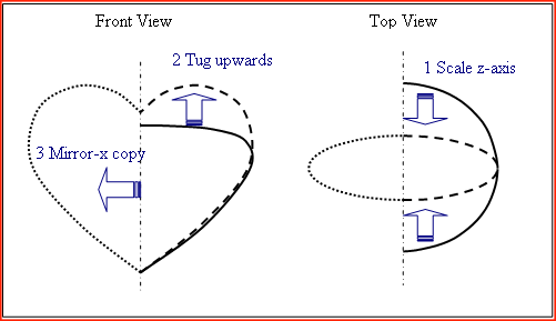
Then modify the basic shape using scaling and tugging to get the desired heart
shape.
Because a clean crease is required between the lobes at the top of the heart it
is easier to make just the right half first. The left half is then simply a
mirror copy of the right.
Step By Step Instructions
1. Create a new smls file
-
i. Start Seamless
-
ii. Create a new smls file called heart:
-
Move the mouse to the top left corner of the 3D scene window to bring up the
main menu
-
Select file->new
-
Navigate to a folder where you want to save your seamless heart
-
Enter heart in the File name box and click on the Save
button
-
iii. Display the Scene Tree and Control Panel:
-
Select scene tree from the main menu
-
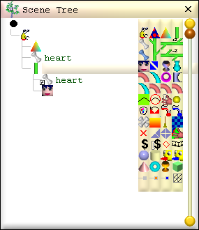
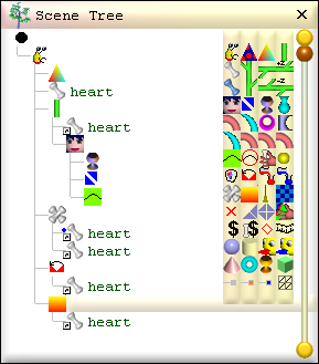
Notice seamless has automatically added some nodes to the Scene Tree.
The big black dot is the Scene node, the yellow and red hoppy is the Seamless
node, the coloured triangle is a ColorEffect node and the white bone is
a Part node.
-
You can click on any node in the Scene Tree to select it and display its
settings in the Control Panel.
2. Create the skeleton of Part nodes
-
A Part node is a container which holds the triangles that form
the surface of a 3D shape. The heart is made using just one Part node and this
was automatically added to the Scene Tree when the new smls file was created.
-
i. Name the part 'heart':
-
Click to the right of the Part node in the Scene Tree and enter heart
-
The name 'heart' can now be used to refer to this part when building its shape.
3. Create the Stem and SurfaceGenerator build
nodes
-
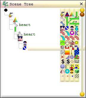
A build node is used to create and model the triangles in a part node.
Note: If you accidentally add the wrong type of node, simply delete it by right
clicking on the unwanted node and selecting delete from the pop-up menu.
-
i. Add a Stem node to the Seamless node's build list:
-
Right click on the Seamless node and select paste->build->new->Stem from the pop-up menu.
-
The Stem node is used to generate a triangle grid which forms the surface of a
part. The surface can then be modelled to the desired shape using surface generator nodes.
-
ii. Setup the Stem to use the heart Part node:
-
Right click on the 'heart' Part and select copy.
-
Right click on the Stem node and select paste->part->USE heart.
-
A SurfaceGenerator node can contain generator nodes which successively modify
the shape of the surface; i.e. the triangle grid created by the Stem node.
-
iii. Add a SurfaceGenerator to the Stem node:
-
Right click on the Stem node and select paste->surface->new->SurfaceGenerator.
-
iv. Save the changes to the smls file:
-
Move the mouse to the top left corner of the 3D scene window to bring up the
main menu
-
Select file->save from the main menu
-
4. Model the basic heart shape
-
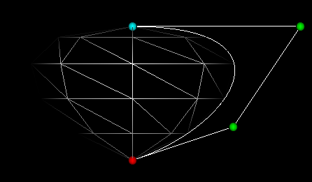
A lathe node allows you to define the profile of a shape somewhat like turning a piece
of wood using a wood lathe. The BezierLathe is used here to create a simple
shape that will make a good basis for the heart. The profile of the basic heart
shape is defined by a set of carefully placed control points. These control
points tug the profile curve into the desired shape.
-
i. Add a BezierLathe to the SurfaceGenerator:
-
Right click on the SurfaceGenerator and select
paste->generator->new->BezierLathe
-
ii. Setup the BezierLathe to have 4 control points:
-
Click on the BezierLathe node to display its settings in the Control Panel
-
Use the length up/down buttons to increment length to 4
-
Each of the control points is given an index number starting from 0.
Always use the index up/down buttons to select which control point to edit.
-
iii. Locate the first control point at the bottom centre of the heart:
-
In the Control Panel, decrement index to 0
-
Set point to 0 0
-
iv. Locate the remaining 3 control points to define the desired
basic heart shape:
-
In the Control Panel set:
point at index 1 to .3 .1
point at index 2 to .5 .4
point at index 3 to 0 .4
-
v. Save the smls file
-
Select file->save from the main menu
-
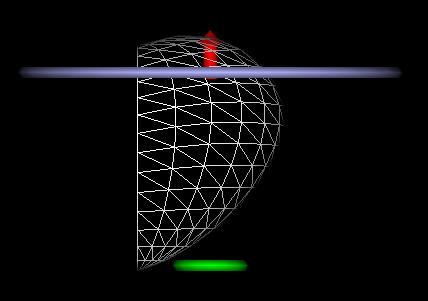
5. Setup the triangle grid
-
The surface of the basic heart shape is made from a flat grid of triangles.
The BezierLathe node wraps the triangle grid into a cylinder and scales its radius
according to the control points.
When the width of the triangle grid is the circumference of a unit circle the grid
will wrap all the way around the cylinder. But because only the right half of the
heart is required, the width of the triangle grid must be set to half the circumference
of a unit circle (i.e. 3.141593).
The Stem node is used to control the location and size of the
triangle grid. The density of the triangles is also set using the Stem node.
-
i. Set the width of the triangle grid to half a unit circle
circumference:
-
Click on the Stem node then, in the Control Panel, set xDistance to 3.141593
-
ii. Locate the triangle grid so that the surface starts a quarter of
the way around the cylinder:
-
iii. Make it so the left and right sides of the triangle grid are not
joined:
-
iv. Increase the number of triangle columns and rows in the grid to
get a smoothly rendered surface:
-
Set staves to 12 and bands 15
-
v. Setup the grid for a shape with a closed bottom and top
i.e. begin and end at single points:
-
vi. Save the smls file
6. Flatten the heart
-
The SurfaceTransform node can, among other things, scale a shape along the
z-axis. This has the effect of flattening out the heart.
-
i. Add a SurfaceTransform to the SurfaceGenerator:
-
Right click on the SurfaceGenerator and select
paste->generator->new->SurfaceTransform
-
ii. Set the z-axis scale to half that of the x-axis scale:
-
Click on the SurfaceTransform node and set the scale to 1 1 .5 in the Control
Panel
-
7. Make the heart lobe
-
The lobe of the heart is made by tugging the top of the basic shape upwards.
The SineTug node can do this very nicely. It behaves a bit like a gravity field; the
closer a vertex is to a control point the more it is pulled in the direction of
the tug displacement.
It is important to tug the lobe directly upwards so that the left
and right sides of the heart will join properly later on.
-
i. Add a SineTug to the SurfaceGenerator:
-
Right click on the SurfaceGenerator and select paste-> generator->new->SineTug
-
ii. Create a single tug control point:
-
Click on the SineTug node and increment length to 1 in the Control Panel
-
iii. Locate the tug point at the top of the heart and to the right:
-
iv. Set the distance of the tug:
-
v. Set the area of the tug:
-
Set radius to .4
-
Set decay to .4
-
vi. Save the smls file
-
8. Create the left side of the heart
-
The left half of the heart is simply a mirror image of the right.
The CopyPart
node is used to copy the triangles on the right side of the heart to make the
left side.
-
i. Add a CopyPart build node:
-
Right click on the Seamless node and select
paste->build->new->CopyPart
-
ii. Setup the CopyPart to copy the triangles from the heart part:
-
Right click on the heart part and select Copy
-
Right click on the CopyPart and select paste->source->USE heart
-
iii. Setup the CopyPart to copy the triangles to heart part:
-
Right click on the heart part and select Copy
-
Right click on the CopyPart and select paste->dest->USE heart
-
iv. Make the copied triangles a mirror image of the right:
-
Check the mirrorX box in the Control Panel
-
v. Make the CopyPart leave the triangles in the right half of
the heart in place:
-
Check the add box in the Control Panel
-
vi. Save the smls file
9. Join the two halves together
-
From the main menu, select cursor/view control->toggle wireframe mode to
display the heart as a solid then right click on the heart in the 3D window and drag
the mouse to the left to rotate it a little.
Notice the seam down the centre of the heart. This is visible because the triangles on
either side of the seam are not joined; they are just very close together.
The JoinVertex node is used to join the vertices of adjacent triangles.
-
i. Add a JoinVertex build node:
-
Right click on the Seamless node and select
paste->build->new->JoinVertex
-
ii. Setup the JoinVertex to use the heart part:
-
Copy the heart part then right click on the JoinVertex and select
paste->part->USE heart
-
iii. Set the maximum distance between vertices to be joined to a suitably
small value:
-
Use the default range of .001
-
iv. Enable the JoinVertex build:
-
Check the in box in the Control Panel
-
v. Save the smls file
10. Add Colour
-
The ColorSweep node is used to set the colour of a part. The colour can 'sweep'
from one colour to another. The heart is a single colour so the begin and end
colours are the same.
-
i. Add a ColorSweep build node:
-
Right click on the Seamless node and select paste->build->new->ColorSweep
-
ii. Setup the ColorSweep to use the heart part:
-
Copy the heart part then right click on the ColorSweep and select
paste->part->USE heart
-
iii. Set the begin colour to deep red:
-
Increment the length field to 2
-
Decrement index to 0
-
Set color to .7 0 0
-
iv. Sweep the color along the y-axis:
-
v. Set the end colour to deep red at the top of the heart:
-
Increment index to 1
-
Set color to .7 0 0
-
Set distance to .5
-
vi. Save the smls file
-

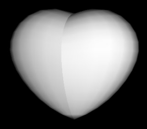
11. Fine tune the triangle density (optional)
-
Notice the edge just visible in the shading near the bottom of the heart in the figure
above. This edge occurs because the triangle bands are too sparse for the level of curvature
in this region. The top of the heart also has this problem, though it is less obvious.
Increasing the total number of triangles using the Stem's bands field improves
things but this is at the expense of many more triangles.
The control points of the BezierLathe can affect the distribution of the bands of
triangles in the triangle grid. By adding two more control points to the BezierLathe node
it is possible to increase the density of triangles where they are needed. This gives a
smoother look to the heart shape without the need for any more triangles.
-
i. Add a BezierLathe control point near to the bottom of the
heart:
-
Click on the BezierLathe, decrement index to 0 and increment length to
5
-
ii. Locate the new control point close to the first one:
-
Set point at index 1 to .01 .001
-
iii. Add a BezierLathe control point near to the top of the heart:
-
Increment index to 3 and increment length to 6
-
iv. Locate the control point close to the last one:
-
Set point at index 4 to .15 .4
-
v. Save the smls file
-

Customising the Heart
By changing the settings of the BezierLathe, SineTug,
SurfaceTransform and ColorSweep it is easy to make almost any heart
shape and colour you desire.
Try adding more control points to the BezierLathe and dragging them with the mouse or increasing the distance of the SignTug.
Remember to save the heart smls file as a different name before experimenting
to avoid overwriting the one you made here.

Bumpy